Prelab
· Desired wiring sketch:
·

· Battery: the battery is 3.7v, which is within the required range of the motor driver (from 2.7 V to 10.8 V). We uses two different batteries for the Artemis and motors because the motors can produce back-EMF when it is rotated passively, this will produce fluctuations in current and voltage, which may damage the Artemis borad.
Lab
1. Photo of my power supply and oscilloscope connection:
o

o
Power
supply’s cathode and anode are connected to the battery’s position, respectively;
the oscilloscope’s cathode(negative) is connected to the anode(negative) of
power supply to ensure the reference is correct, but the oscilloscope’s positive
end is hooked to motor’s positive end to measure the output from motor driver to
motor.
o
Originally,
I hooked the oscilloscope’s ground end to motor’s negative end, but there were
some EMI noises. So, I changed the oscilloscope’s ground end to power supply’s
negative end to get the same diagram but with less noise.
2. The power supply’s output should be set to 3.7v, the same as the battery’s voltage to get the best simulation effects. Also, as discussed previously, this is within the allowed range of motor drivers.
3. After setting up the connection between the motor drivers and Artemis, I tested its functionality with the following codes. I first set all the pins used to OUTPUT in the setup, then in the loop I keep negative pin 3,7 in 0 while switch positive pin 2,6 between 0 and 255, every half second.
o

4. And the graph from oscilloscope has clear edges:
o

5. After connecting one of the motors with the Artemis and the driver, I can power the wheels on one side. As the video shows, I used pin 6,7 part of the code shown above.
o
6. Then do the same thing for the other side, and connect the motor driver to battery rather than the power supply, using the whole code snippet shown in step 3:
o
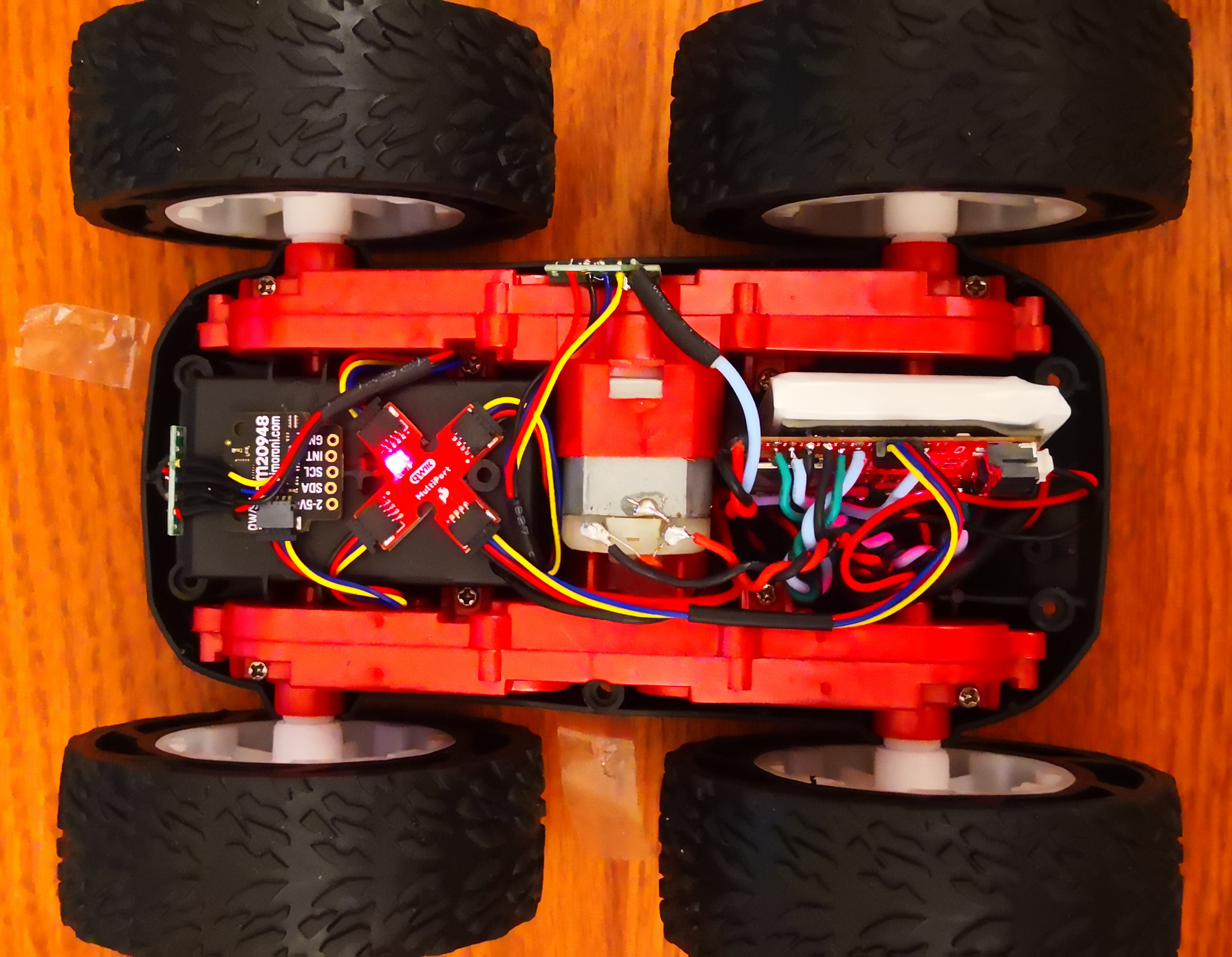
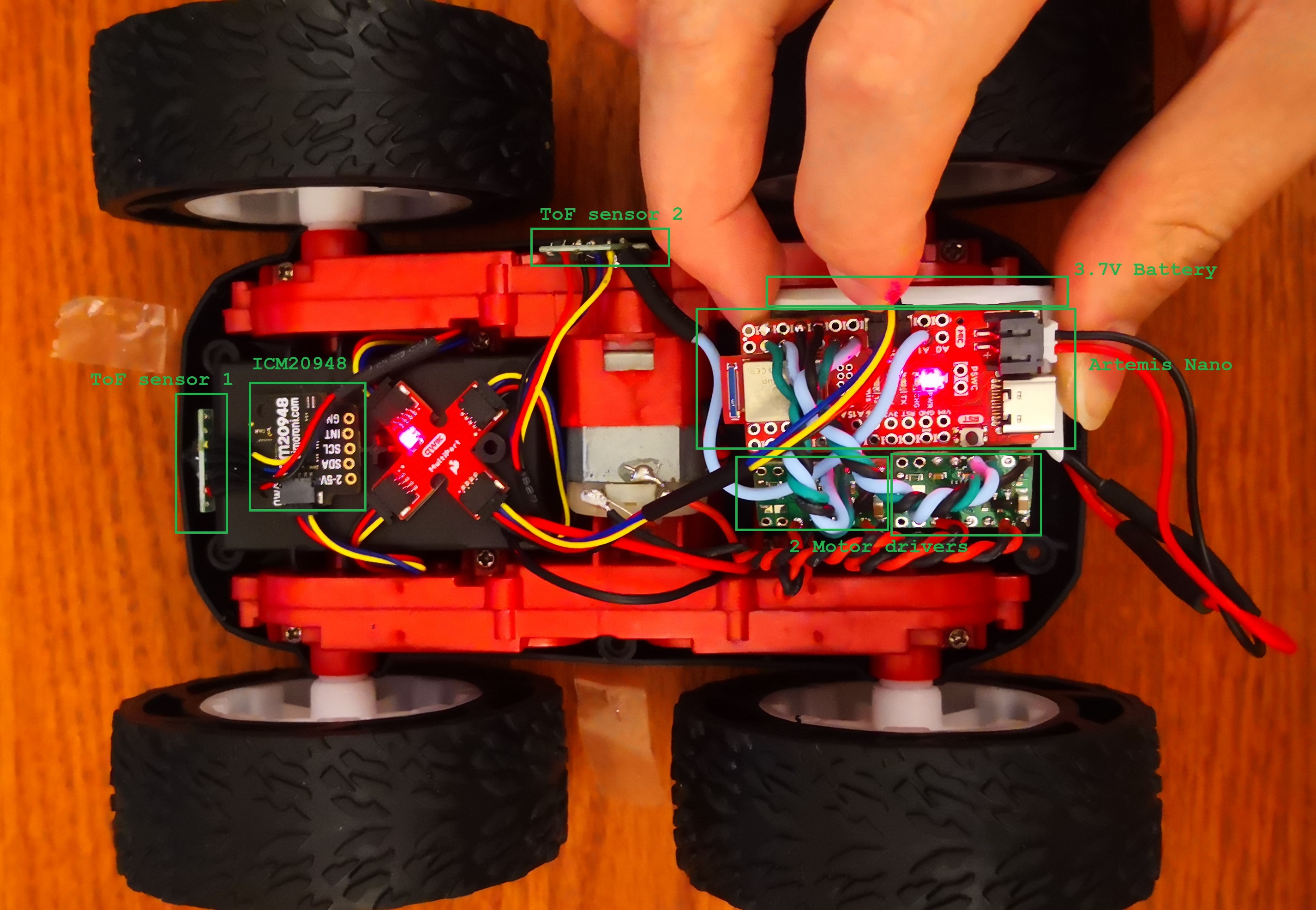
7. After soldering and connecting all chips and sensors in position, my car was ready to go:


8. Lower limit PWM value:
o Started from 50, I gradually decrease the PWM, and the lowest PWM that allows the car to move is 30:
o
9. After I extend the running time from 1 s to 2 s and compare with a straight line on the ground, I found the car was not following the straight line—its left wheels spin significantly slower than right side. After repeatedly trials, I found that multiplying the right side with a factor 0.7 can make it drive forward straightly. I tested this by comparing car’s track with the straight line on the wooden ground. The distance between the box and the black plastic is 2.08 meters.
o

o
o I also checked if the car is able to spin in place:
o
10. To verify the car can drive itself, I implemented the following codes to test:
o

o And the car runs well. The code above tests the car on both on-axis(turning by 2 sides wheels spin oppositely) turn left &right and go forward straightly. As the video below shows, the car does all of these well, although I don’t have method to the accurately control the turning degree so far—that will be done by PID control.
o